|

|
|
WiPAN LVSA - LR-WPAN
Signal Analysis and Measurement Tool/Overview |
|

 |
The analysis of
signals is a fundamental problem for many engineers and
scientists. Often a large engineering effort is spent in analyzing
the wireless systems. For engineers working with today’s emerging
ZigBee technology, Seasolve’s signal analyzer software WiPAN LVSA
is an indispensable tool for research, product development and
product manufacturing. Now Perform advanced analysis of transmit
and receive designs with a flexible and cost-effective analysis
solution - WiPAN LVSA. It provides baseband (I/Q) analysis & RF
analysis using the vector signal analyzer (NI PXI RFSA 5660). |
|
 |
|
MEASUREMENT
FEATURES |
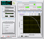
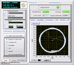
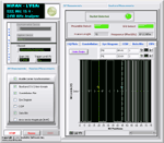
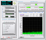
 Power Spectrum Power Spectrum
Constellation
EVM
CCDF
Eye Diagram
Time Domain
RF Power Spectrum
Power In Band
Adjacent channel power (both
lower and higher)
Occupied Bandwidth
The WiPAN LVSA signal analysis software is a LabVIEW design, to
measure and analyze the RF and Baseband signals in the 2.4 GHz band
using NI PXI RFSA 5660. It’s a WPAN Baseband PHY receiver software
capable of capturing signals, performing symbol synchronization,
frequency synchronization and neutralizing front end non idealities.
The receiver also performs EVM calculation as per standard
specifications.
|
|
|
|
HIGHLIGHTS |
Fast and accurate analysis
Real time data display, with
real time simulation of the results
Zoom function for increased
detail
AutoSpan – fit to window
Custom Trigger level
Friendly user interface -
spend less time on testing the device
Simpler Connectivity between
devices
Examine Symbol behavior with
eye diagrams
Error Vector Magnitude (EVM)
spectrum and time plots for sensitive examination of signal errors.
Constellation diagrams for an
overall indication of signal behavior and clues to the cause of a
problem.
Signal analysis in Time and
Frequency domains to analyze changing phase, magnitude and frequency
RF Input Frequency range -
2.4 GHz band ( 16 channels)
Supports Graphic Utilities
like changing plot color, markers etc
Displays frame length
Analyzer provides for packet
detection, offset correction, channel estimation & correction.
|
|
|
|
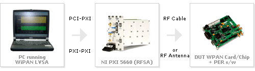
SIGNAL
GENERATION SETUP FOR WPAN RECEIVER TESTING |
|
|
|
|
|
SYSTEM
REQUIREMENTS |
System Memory: Minimum 512
MB, recommended 1GB
Disk Space: 100 MB
OS: Windows 2000/NT/XP
NI-PXI 5660 RF Signal
Analyzer
Drivers : NI PXI 5660 RFSA
ver 1.5
|
|
|
|
BENEFITS |
Evaluate Transmitter/Receiver
design as per the IEEE standards
Take advantage of
standardized tests to qualify parts and perform acceptance testing.
Use the software for
manufacturing tests
Verification of chip designs
WPAN Equipment manufacturers can take
advantage of WiPAN LVCT to ensure reliable interoperability
between WPAN products from different vendors.
Researchers and Students can
carry their research on IEEE 802.15.4(2.4 GHz) WPAN with ease and come
out with best results
Certifying Labs can test and
certify WPAN chips from various manufacturers and benchmark their
performance
IP vendors can validate their
WPAN IP for market acceptance.
Generates accurate data which
helps the designers to test Receiver performance with ease
Easy to use GUI
Designers can move quickly
from simulation domain to generation of real world WPAN systems
Seamless integration with NI
PXI 5660 RFSA
|
|
|
|
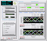
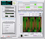
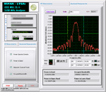
Screenshots |
|
|
|
|